
Difficult
Seven capacitors,each of capacitance $2\ \mu F$,are connected in such a way that the total equivalent capacitance is $\frac{10}{11}\ \mu F$. Which of the following circuit diagrams represents this arrangement?
- A
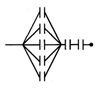
- B
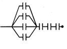
- C
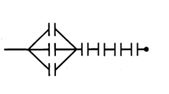
- D
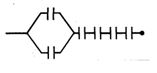
Explore More
Similar Questions
Two capacitors of capacitances $1 \ \mu F$ and $2 \ \mu F$ are charged to potential differences $20 \ V$ and $15 \ V$ as shown in the figure. If terminals $B$ and $C$ are connected together and terminals $A$ and $D$ are connected together,then find the final charge on the $1 \ \mu F$ capacitor.
Medium
View Solution$A$ flat circular disc has a charge $+Q$ uniformly distributed on it. $A$ charge $+q$ is thrown with kinetic energy $E$ towards the disc along its normal axis. The charge $q$ will:
Easy
View SolutionIn the given circuit,$C_1=2\,\mu F, C_2=0.2\,\mu F, C_3=2\,\mu F, C_4=4\,\mu F, C_5=2\,\mu F, C_6=2\,\mu F$. The charge stored on capacitor $C_4$ is $.....\mu C$.
Seven capacitors,each of capacity $2\,\mu F$,are to be connected to have a total capacity of $\frac{10}{11}\,\mu F$. Which of the following figures shows the correct arrangement?
MediumIIT 1990
View Solution$A$ network of four capacitors with capacitances $C_1 = C$,$C_2 = 2C$,$C_3 = 3C$,and $C_4 = 4C$ is connected to a battery of potential $V$ as shown in the figure. The ratio of the charges on $C_2$ and $C_4$ is:
MediumAIIMS 2012
View SolutionVedclass Products
For Students
Vedclass Test Series
Mock tests in real JEE/NEET style with performance analysis. 5-day free trial.
Start Free TrialFor Teachers
Exam Paper Generator
Generate Set A/B/C/D exam papers from 7.5L+ questions in 2 minutes. 3 chapters free.
Try FreeFor Institutes
Online Exam Module
Live online exams with unlimited students, 360° analytics & white-label branding.
See Demo