
$A$ short bar magnet passes at a steady speed right through a long solenoid. $A$ galvanometer is connected across the solenoid. Which graph best represents the variation of the galvanometer deflection $\theta$ with time $t$?
- A
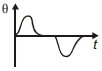
- B
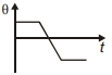
- C
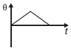
- D

Explore More
Similar Questions
$A$ coil of wire having finite inductance and resistance has a conducting ring placed coaxially within it. The coil is connected to a battery at time $t = 0$,so that a time-dependent current $I_1(t)$ starts flowing through the coil. If $I_2(t)$ is the current induced in the ring and $B(t)$ is the magnetic field at the axis of the coil due to $I_1(t)$,then as a function of time $(t > 0)$,the product $I_2(t) B(t)$:
DifficultIIT 2000
View Solution$A$ conducting square loop initially lies in the $XZ$ plane with its lower edge hinged along the $X$-axis. Only in the region $y \geq 0$,there is a time-dependent magnetic field pointing along the $Z$-direction,$\vec{B}(t) = B_0(\cos \omega t) \hat{k}$,where $B_0$ is a constant. The magnetic field is zero everywhere else. At time $t=0$,the loop starts rotating with constant angular speed $\omega$ about the $X$-axis in the clockwise direction as viewed from the $+X$ axis (as shown in the figure). Ignoring self-inductance of the loop and gravity,which of the following plots correctly represents the induced e.m.f. $(V)$ in the loop as a function of time?
Two long parallel wires whose centres are at a distance $d$ apart carry equal currents in opposite directions. If the flux within the wires is neglected,the inductance of such an arrangement of wire of length $l$ and radius $a$ will be
$A$ conducting loop in the form of a circle is placed in a uniform magnetic field with its plane perpendicular to the direction of the field. An emf will be induced in the loop, if
MediumWBJEE 2015
View SolutionThe circuit shown in the figure contains an inductor $L = 25 \text{ mH}$, a capacitor $C_0 = 10 \text{ } \mu\text{F}$, a resistor $R_0 = 5 \text{ } \Omega$ and an ideal battery of $20 \text{ V}$. The circuit also contains two keys $K_1$ and $K_2$. Initially, both the keys are open and there is no charge on the capacitor. At an instant, key $K_1$ is closed and immediately after this, the current in $R_0$ is found to be $I_1$. After a long time, the current attains a steady state value $I_2$. Thereafter, $K_2$ is closed and simultaneously $K_1$ is opened, and the voltage across $C_0$ oscillates with amplitude $V_0$ and angular frequency $\omega_0$. Match the quantities mentioned in $List-I$ with their values in $List-II$ and choose the correct option.
$List-I$ $List-II$ $(P)$ The value of $I_1$ in Ampere is $(1)$ $0$ $(Q)$ The value of $I_2$ in Ampere is $(2)$ $2$ $(R)$ The value of $\omega_0$ in kilo-radians/s is $(3)$ $4$ $(S)$ The value of $V_0$ in Volt is $(4)$ $20$ $(5)$ $200$
| $List-I$ | $List-II$ |
| $(P)$ The value of $I_1$ in Ampere is | $(1)$ $0$ |
| $(Q)$ The value of $I_2$ in Ampere is | $(2)$ $2$ |
| $(R)$ The value of $\omega_0$ in kilo-radians/s is | $(3)$ $4$ |
| $(S)$ The value of $V_0$ in Volt is | $(4)$ $20$ |
| $(5)$ $200$ |
MediumIIT 2024
View SolutionVedclass Products
For Students
Vedclass Test Series
Mock tests in real JEE/NEET style with performance analysis. 5-day free trial.
Start Free TrialFor Teachers
Exam Paper Generator
Generate Set A/B/C/D exam papers from 7.5L+ questions in 2 minutes. 3 chapters free.
Try FreeFor Institutes
Online Exam Module
Live online exams with unlimited students, 360° analytics & white-label branding.
See Demo