
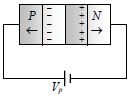
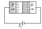
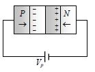
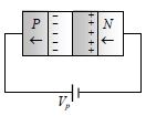
In the case of forward biasing of a $PN-$ junction,which one of the following figures correctly depicts the direction of flow of majority charge carriers?
- A
- B
- C
- D
Explore More
Similar Questions
Two ideal diodes are connected to a battery as shown in the circuit. The current supplied by the battery is: (in $A$)
Medium
View SolutionThe length of a germanium rod is $0.925 \ cm$ and its area of cross-section is $1 \ mm^2$. If for germanium $n_i = 2.5 \times 10^{19} \ m^{-3}$,$\mu_h = 0.19 \ m^2/V\cdot s$,and $\mu_e = 0.39 \ m^2/V\cdot s$,then the resistance of the rod is:
DifficultAP EAMCET 2021
View SolutionExplain the forward and reverse characteristics of the $p-n$ junction diode by drawing the circuit and graph.
$A$ waveform is applied to the following circuit. Assuming an ideal diode and ${R_1} = {R_2}$, which of the following output waveforms will be produced?
Medium
View SolutionThree identical p-n junction diodes $D_1$, $D_2$ and $D_3$ are connected across a battery as shown in the figure. If the widths of the depletion regions of $D_1$, $D_2$ and $D_3$ are $W_1$, $W_2$ and $W_3$, respectively, then the correct option is:
MediumNEET 2026
View SolutionVedclass Products
For Students
Vedclass Test Series
Mock tests in real JEE/NEET style with performance analysis. 5-day free trial.
Start Free TrialFor Teachers
Exam Paper Generator
Generate Set A/B/C/D exam papers from 7.5L+ questions in 2 minutes. 3 chapters free.
Try FreeFor Institutes
Online Exam Module
Live online exams with unlimited students, 360° analytics & white-label branding.
See Demo