
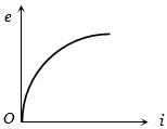
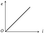
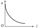
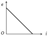
For the previous objective,which of the following graphs is correct?
- A
- B
- C
- D
Explore More
Similar Questions
Two resistors of $6\,\Omega$ and $9\,\Omega$ are connected in series to a $120\,V$ source. The power consumed by the $6\,\Omega$ resistor is ........... $W$.
Medium
View SolutionEach element in the finite chain of resistors shown in the figure is $1\,\Omega $. $A$ current of $1\, A$ flows through the final element. Then what is the potential difference $V$ across input terminals of the chain (in $,V$)?
Medium
View SolutionThe figure shows a network of resistances in which the point $A$ is earthed. The current through the $3\,\Omega$ resistor is
Difficult
View SolutionConsider an infinite ladder network shown in the figure. $V$ voltage $V$ is applied between the points $A$ and $B$. This applied voltage is halved after each section.
Difficult
View SolutionThe diagram shows a circuit used in an experiment to determine the $emf$ $(E)$ and internal resistance $(r)$ of the cell $C$. $A$ graph was plotted of the potential difference $V$ between the terminals of the cell against the current $I$,which was varied by adjusting the rheostat. The graph is shown on the right; $x$ and $y$ are the intercepts of the graph with the axes as shown. What is the internal resistance of the cell?
Difficult
View SolutionVedclass Products
For Students
Vedclass Test Series
Mock tests in real JEE/NEET style with performance analysis. 5-day free trial.
Start Free TrialFor Teachers
Exam Paper Generator
Generate Set A/B/C/D exam papers from 7.5L+ questions in 2 minutes. 3 chapters free.
Try FreeFor Institutes
Online Exam Module
Live online exams with unlimited students, 360° analytics & white-label branding.
See Demo