
Switch $S$ of the circuit shown in the figure is closed at $t = 0$. If $e$ denotes the induced $emf$ in $L$ and $i$ the current flowing through the circuit at time $t$,which of the following graphs is correct?
- A
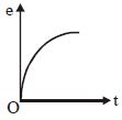
- B
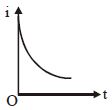
- C
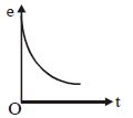
- D
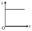
Explore More
Similar Questions
For the given circuit,the current through the battery of $6\,V$ just after closing the switch $S$ will be $.......A$.
The total heat produced in resistor $R$ in an $RL$ circuit when the current in the inductor decreases from $I_0$ to $0$ is
Easy
View SolutionIn the given circuit,the sliding contact is pulled outwards such that the electric current in the circuit changes at the rate of $8 \text{ A/s}$. At an instant when $R = 12 \Omega$,the value of the current in the circuit will be . . . . . . $A$.
An inductor of inductance $L = 400 \ mH$ and resistors of resistance $R_1 = 2 \ \Omega$ and $R_2 = 2 \ \Omega$ are connected to a battery of emf $E = 12 \ V$ as shown in the figure. The internal resistance of the battery is negligible. The switch $S$ is closed at $t = 0$. The potential drop across $L$ as a function of time is:
DifficultAIEEE 2009
View SolutionIn an $L-R$ decay circuit,the initial current at $t = 0$ is $I$. The total charge that has flown through the resistor until the energy in the inductor has reduced to one-fourth of its initial value is:
Vedclass Products
For Students
Vedclass Test Series
Mock tests in real JEE/NEET style with performance analysis. 5-day free trial.
Start Free TrialFor Teachers
Exam Paper Generator
Generate Set A/B/C/D exam papers from 7.5L+ questions in 2 minutes. 3 chapters free.
Try FreeFor Institutes
Online Exam Module
Live online exams with unlimited students, 360° analytics & white-label branding.
See Demo