
A English
Mix Examples - Electricity Questions in English
Class 10 Science · Electricity · Mix Examples - Electricity
43+
Questions
English
Language
100%
With Solutions
Showing 43 of 43 questions in English
1
DifficultMCQ
Two conducting wires of the same material and of equal lengths and equal diameters are first connected in series and then parallel in a circuit across the same potential difference. The ratio of heat produced in series and parallel combinations would be -
A
$1:2$
B
$1:4$
C
$2:1$
D
$4:1$
Solution
(B) Heat produced in the circuit is inversely proportional to the resistance $R$ for a constant potential difference $V$,given by the formula $H = \frac{V^2}{R} t$.
Let $R$ be the resistance of each wire. If connected in series,the equivalent resistance is $R_S = R + R = 2R$.
If connected in parallel,the equivalent resistance is $R_P = \frac{R \times R}{R + R} = \frac{R}{2}$.
The ratio of heat produced in series $(H_S)$ to parallel $(H_P)$ is given by:
$\frac{H_S}{H_P} = \frac{V^2 / R_S \times t}{V^2 / R_P \times t} = \frac{R_P}{R_S}$.
Substituting the values of $R_S$ and $R_P$:
$\frac{H_S}{H_P} = \frac{R/2}{2R} = \frac{1}{4}$.
Thus,the ratio of heat produced is $1:4$.
0 likes
View Solution2
Difficult
$A$ hot plate of an electric oven connected to a $220\, V$ line has two resistance coils $A$ and $B$,each of $24\,\Omega$ resistance,which may be used separately,in series,or in parallel. What are the currents in the three cases?
Solution
(N/A) Supply voltage,$V = 220\, V$.
Resistance of each coil,$R = 24\,\Omega$.
$(i)$ When coils are used separately:
According to Ohm's law,$I = V / R$.
$I_1 = 220 / 24 = 9.17\, A$.
$(ii)$ When coils are connected in series:
Total resistance,$R_s = R + R = 24 + 24 = 48\,\Omega$.
$I_2 = V / R_s = 220 / 48 = 4.58\, A$.
$(iii)$ When coils are connected in parallel:
Total resistance,$1 / R_p = 1 / R + 1 / R = 1 / 24 + 1 / 24 = 2 / 24 = 1 / 12$.
So,$R_p = 12\,\Omega$.
$I_3 = V / R_p = 220 / 12 = 18.33\, A$.
0 likes
View Solution3
DifficultMCQ
Compare the power used in the $2 \,\Omega$ resistor in each of the following circuits: $(i)$ a $6 \,V$ battery in series with $1 \,\Omega$ and $2 \,\Omega$ resistors,and $(ii)$ a $4 \,V$ battery in parallel with $12 \,\Omega$ and $2 \,\Omega$ resistors.
A
Power in $(i)$ is greater than $(ii)$
B
Power in $(ii)$ is greater than $(i)$
C
Power in $(i)$ is equal to $(ii)$
D
Power in $(i)$ is half of $(ii)$
Solution
(C) Case $(i)$: Potential difference,$V = 6 \,V$. The $1 \,\Omega$ and $2 \,\Omega$ resistors are connected in series. The equivalent resistance $R = 1 + 2 = 3 \,\Omega$. According to Ohm's law,$I = V/R = 6/3 = 2 \,A$. In a series circuit,the current remains the same through all components. Thus,the current through the $2 \,\Omega$ resistor is $2 \,A$. Power $P = I^2 R = (2)^2 \times 2 = 8 \,W$.
Case $(ii)$: Potential difference,$V = 4 \,V$. The $12 \,\Omega$ and $2 \,\Omega$ resistors are connected in parallel. In a parallel circuit,the voltage across each component is the same as the source voltage. Thus,the voltage across the $2 \,\Omega$ resistor is $4 \,V$. Power $P = V^2/R = (4)^2/2 = 16/2 = 8 \,W$.
Conclusion: The power used in the $2 \,\Omega$ resistor is $8 \,W$ in both cases.
0 likes
View Solution4
MediumMCQ
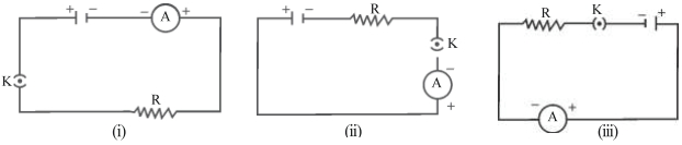
$A$ cell,a resistor,a key and an ammeter are arranged as shown in the circuit diagrams of the figure. The current recorded in the ammeter will be
A
The same in all the cases
B
maximum in $(i)$
C
maximum in $(ii)$
D
maximum in $(iii)$
Solution
(A) According to Ohm's Law,the current $I$ in a series circuit is given by $I = V/R$,where $V$ is the potential difference (voltage of the cell) and $R$ is the total resistance of the circuit.
In all three circuit diagrams $(i)$,$(ii)$,and $(iii)$,the components (cell,resistor,key,and ammeter) are connected in series.
Since the components are the same and they are connected in series,the total resistance $R$ and the total voltage $V$ remain constant in all three cases.
Therefore,the current $I$ flowing through the circuit will be the same in all three cases.
0 likes
View Solution5
MediumMCQ
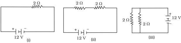
In the following circuits (Figure),heat produced in the resistor or combination of resistors connected to a $12\, V$ battery will be
A
minimum in case $(i)$
B
same in all the cases
C
maximum in case $(ii)$
D
maximum in case $(iii)$
Solution
(D) The heat produced in a circuit is given by the formula $H = \frac{V^2}{R} \times t$,where $V$ is the potential difference,$R$ is the equivalent resistance,and $t$ is the time.
Since $V = 12\, V$ is constant for all cases,the heat produced $H$ is inversely proportional to the equivalent resistance $R$ $(H \propto \frac{1}{R})$.
Case $(i)$: $A$ single resistor of $2\, \Omega$. Equivalent resistance $R_1 = 2\, \Omega$.
Case $(ii)$: Two resistors of $2\, \Omega$ each connected in series. Equivalent resistance $R_2 = 2\, \Omega + 2\, \Omega = 4\, \Omega$.
Case $(iii)$: Two resistors of $2\, \Omega$ each connected in parallel. Equivalent resistance $R_3 = \frac{2 \times 2}{2 + 2} = \frac{4}{4} = 1\, \Omega$.
Comparing the resistances: $R_3 (1\, \Omega) < R_1 (2\, \Omega) < R_2 (4\, \Omega)$.
Since $H \propto \frac{1}{R}$,the heat produced will be maximum where the resistance is minimum.
Therefore,the heat produced is maximum in case $(iii)$ because it has the lowest equivalent resistance $(1\, \Omega)$.
0 likes
View Solution6
Medium
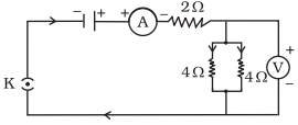
Draw a circuit diagram of an electric circuit containing a cell,a key,an ammeter,a resistor of $2\,\Omega$ in series with a combination of two resistors ($4\,\Omega$ each) in parallel and a voltmeter across the parallel combination. Will the potential difference across the $2\,\Omega$ resistor be the same as that across the parallel combination of $4\,\Omega$ resistors? Give reason.
Solution
(A) Yes,the potential difference will be the same.
First,calculate the equivalent resistance of the parallel combination of two $4\,\Omega$ resistors:
$\frac{1}{R_p} = \frac{1}{4} + \frac{1}{4} = \frac{2}{4} = \frac{1}{2}$
So,$R_p = 2\,\Omega$.
Since the $2\,\Omega$ resistor is in series with the parallel combination (which also has an equivalent resistance of $2\,\Omega$),the same current $I$ flows through both. According to Ohm's Law $(V = IR)$,since the resistance values are equal $(2\,\Omega = 2\,\Omega)$ and the current $I$ is the same,the potential difference across both will be equal.
0 likes
View Solution7
MediumMCQ
$A$ current of $1 \ A$ flows in a series circuit containing an electric lamp and a conductor of $5 \ \Omega$ when connected to a $10 \ V$ battery. Calculate the resistance of the electric lamp. Now,if a resistance of $10 \ \Omega$ is connected in parallel with this series combination,what change (if any) in the current flowing through the $5 \ \Omega$ conductor and the potential difference across the lamp will take place? Give reason.
A
Resistance of lamp is $5 \ \Omega$; no change in current or potential difference.
B
Resistance of lamp is $10 \ \Omega$; current through $5 \ \Omega$ conductor decreases.
C
Resistance of lamp is $5 \ \Omega$; current through $5 \ \Omega$ conductor increases.
D
Resistance of lamp is $2 \ \Omega$; potential difference across lamp changes.
Solution
(A) Step $1$: Calculate the resistance of the lamp.
In a series circuit,total resistance $R_{total} = V / I = 10 \ V / 1 \ A = 10 \ \Omega$.
Since $R_{total} = R_{lamp} + R_{conductor}$,we have $10 \ \Omega = R_{lamp} + 5 \ \Omega$.
Therefore,$R_{lamp} = 5 \ \Omega$.
Step $2$: Analyze the parallel connection.
When a $10 \ \Omega$ resistor is connected in parallel to the series combination,the potential difference across the series combination remains $10 \ V$ because the battery is connected directly across the parallel branches.
Since the potential difference across the series branch (lamp + $5 \ \Omega$ conductor) remains $10 \ V$,the current flowing through the series branch remains $I = V / R_{total} = 10 \ V / 10 \ \Omega = 1 \ A$.
Consequently,there will be no change in the current flowing through the $5 \ \Omega$ conductor,and there will be no change in the potential difference across the lamp.
0 likes
View Solution8
Medium
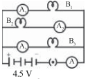
$B_1, B_2$ and $B_3$ are three identical bulbs connected as shown in the figure. When all three bulbs glow,a current of $3\,A$ is recorded by the ammeter $A$.
$(i)$ What happens to the glow of the other two bulbs when the bulb $B_1$ gets fused?
$(ii)$ What happens to the reading of $A_1, A_2, A_3$ and $A$ when the bulb $B_2$ gets fused?
$(iii)$ How much power is dissipated in the circuit when all three bulbs glow together?
$(i)$ What happens to the glow of the other two bulbs when the bulb $B_1$ gets fused?
$(ii)$ What happens to the reading of $A_1, A_2, A_3$ and $A$ when the bulb $B_2$ gets fused?
$(iii)$ How much power is dissipated in the circuit when all three bulbs glow together?
Solution
(N/A) $(i)$ Since the bulbs are connected in parallel,the potential difference across each bulb remains the same $(4.5\,V)$. Therefore,the glow of the bulbs $B_2$ and $B_3$ will remain unchanged when $B_1$ fuses.
$(ii)$ When $B_2$ fuses,the circuit branch containing $B_2$ becomes open. Thus,$A_2$ will show $0\,A$. The other two branches remain unaffected,so $A_1$ will show $1\,A$ and $A_3$ will show $1\,A$. The total current recorded by ammeter $A$ will be $1\,A + 0\,A + 1\,A = 2\,A$.
$(iii)$ The total power dissipated in the circuit is given by $P = V \times I$. Given $V = 4.5\,V$ and total current $I = 3\,A$,we have $P = 4.5\,V \times 3\,A = 13.5\,W$.
0 likes
View Solution9
Medium
Find out the following in the electric circuit given in the figure:
$(a)$ Effective resistance of two $8\,\Omega$ resistors in the combination.
$(b)$ Current flowing through the $4\,\Omega$ resistor.
$(c)$ Potential difference across the $4\,\Omega$ resistor.
$(d)$ Power dissipated in the $4\,\Omega$ resistor.
$(e)$ Difference in ammeter readings,if any.
$(a)$ Effective resistance of two $8\,\Omega$ resistors in the combination.
$(b)$ Current flowing through the $4\,\Omega$ resistor.
$(c)$ Potential difference across the $4\,\Omega$ resistor.
$(d)$ Power dissipated in the $4\,\Omega$ resistor.
$(e)$ Difference in ammeter readings,if any.
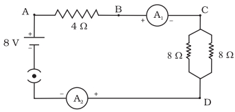
Solution
(N/A) The two $8\,\Omega$ resistors are in parallel. Their effective resistance $R_p$ is given by:
$R_p = \frac{R_1 \times R_2}{R_1 + R_2} = \frac{8 \times 8}{8 + 8} = \frac{64}{16} = 4\,\Omega$.
$(b)$ The total resistance of the circuit $R_{eq} = R_{series} + R_p = 4\,\Omega + 4\,\Omega = 8\,\Omega$. The total current $I$ flowing through the circuit is $I = \frac{V}{R_{eq}} = \frac{8\,V}{8\,\Omega} = 1\,A$. Since the $4\,\Omega$ resistor is in series with the rest of the circuit,the current flowing through it is $1\,A$.
$(c)$ The potential difference $V$ across the $4\,\Omega$ resistor is $V = I \times R = 1\,A \times 4\,\Omega = 4\,V$.
$(d)$ The power dissipated $P$ in the $4\,\Omega$ resistor is $P = I^2 R = (1\,A)^2 \times 4\,\Omega = 4\,W$.
$(e)$ There is no difference in the ammeter readings. In a series circuit,the same amount of current flows through every component.
0 likes
View Solution10
Medium
Explain the following.
$(a)$ Why is the series arrangement not used for domestic circuits?
$(b)$ How does the resistance of a wire vary with its area of cross-section?
$(a)$ Why is the series arrangement not used for domestic circuits?
$(b)$ How does the resistance of a wire vary with its area of cross-section?
Solution
(N/A) In a series circuit,the total voltage is divided among the components. If one component fails or is switched off,the entire circuit breaks,and no current flows. Furthermore,each device receives a lower voltage than required,and the total resistance increases,which reduces the current. Therefore,series arrangement is not used in domestic circuits.
$(b)$ The resistance $(R)$ of a wire is inversely proportional to its area of cross-section $(A)$. This is expressed as $R \propto \frac{1}{A}$. As the area of cross-section increases,the resistance decreases,and vice versa.
$(b)$ The resistance $(R)$ of a wire is inversely proportional to its area of cross-section $(A)$. This is expressed as $R \propto \frac{1}{A}$. As the area of cross-section increases,the resistance decreases,and vice versa.
0 likes
View Solution11
Medium
Read the following statements carefully and state whether each statement is true or false:
$(i)$ The quantity of charge flowing past a point multiplied by time is current.
$(ii)$ The flow of charge through a conducting wire connected to a cell is the result of a chemical reaction inside the cell.
$(iii)$ The resistivity of all pure metals increases with an increase in temperature.
$(iv)$ Ohm's law is a relation between the power used in a circuit to the current and the potential difference.
$(v)$ $A$ series circuit has only one conducting path for the electrons that move through it; a parallel circuit has multiple conducting paths.
$(vi)$ $A$ conducting wire offers resistance to the flow of electrons because electrons repel each other in the wire.
Solution
(A) $(i)$ False: Current is defined as the rate of flow of charge,i.e.,$I = Q/t$. The statement incorrectly suggests $I = Q \times t$.
$(ii)$ True: $A$ cell converts chemical energy into electrical energy through internal chemical reactions,which drives the charge flow.
$(iii)$ True: For pure metals,the resistivity increases as temperature rises due to increased collisions between electrons and vibrating ions.
$(iv)$ False: Ohm's law states that the potential difference across a conductor is directly proportional to the current flowing through it $(V \propto I)$,provided temperature remains constant. It does not relate to power.
$(v)$ True: In a series circuit,there is only one path for current,whereas a parallel circuit provides multiple branches for current flow.
$(vi)$ False: Resistance in a wire is primarily due to the collisions of electrons with the atoms/ions of the conductor's lattice,not due to electron-electron repulsion.
0 likes
View Solution12
EasyMCQ
How is alternating current $(AC)$ different from direct current $(DC)$?
A
Alternating current flows in one direction,while direct current changes direction.
B
Alternating current changes its magnitude and direction periodically,while direct current maintains a constant magnitude and direction.
C
Direct current is used in household appliances,while alternating current is used in batteries.
D
There is no difference between alternating current and direct current.
Solution
(B) Alternating current $(AC)$ is defined as the current that changes its magnitude continuously and reverses its direction periodically over time.
In contrast,direct current $(DC)$ is the current that flows in a single constant direction and maintains a constant magnitude over time.
Therefore,the fundamental difference lies in the periodic reversal of direction and variation in magnitude characteristic of $AC$ compared to the steady nature of $DC$.
0 likes
View Solution13
Medium
$(a)$ Explain the difference between direct current and alternating current. Write one important advantage of using alternating current.
$(b)$ An air conditioner of $2 \,kW$ is used in an electric circuit having a fuse of $10 \,A$ rating. If the potential difference of the supply is $220 \,V$,will the fuse be able to withstand the current when the air conditioner is switched on? Justify your answer.
$(b)$ An air conditioner of $2 \,kW$ is used in an electric circuit having a fuse of $10 \,A$ rating. If the potential difference of the supply is $220 \,V$,will the fuse be able to withstand the current when the air conditioner is switched on? Justify your answer.
Solution
(B) The current whose direction reverses periodically is called alternating current $(AC)$,whereas direct current $(DC)$ flows in a constant direction.
The primary advantage of $AC$ is that it can be transmitted over long distances with minimal power loss compared to $DC$.
$(b)$ Given: Power $(P)$ = $2 \,kW = 2000 \,W$,Voltage $(V)$ = $220 \,V$.
Using the formula $P = VI$,the current $(I)$ is calculated as:
$I = \frac{P}{V} = \frac{2000}{220} \approx 9.09 \,A$.
Since the calculated current $(9.09 \,A)$ is less than the fuse rating of $10 \,A$,the fuse will withstand the current and will not blow off when the air conditioner is switched on.
0 likes
View Solution14
Medium
How are ammeters and voltmeters connected in a circuit? What do they help us measure?
Solution
(N/A) An ammeter is always connected in series with the circuit components. It measures the electric current flowing through the circuit.
$A$ voltmeter is always connected in parallel across the points between which the potential difference is to be measured. It measures the potential difference across a conductor.
$A$ voltmeter is always connected in parallel across the points between which the potential difference is to be measured. It measures the potential difference across a conductor.
0 likes
View Solution15
Difficult
How would the reading of the voltmeter $(V)$ change if it is connected between points $B$ and $C$? Justify your answer.
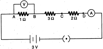
Solution
(N/A) The total resistance of the circuit is $R = R_1 + R_2 + R_3 = 1 \Omega + 3 \Omega + 2 \Omega = 6 \Omega$.
The total current in the circuit is $I = \frac{V}{R} = \frac{3 \text{ V}}{6 \Omega} = 0.5 \text{ A}$.
When the voltmeter is connected between $B$ and $C$,it measures the potential difference across the $3 \Omega$ resistor.
The potential difference across the $3 \Omega$ resistor is $V_{BC} = I \times R_{BC} = 0.5 \text{ A} \times 3 \Omega = 1.5 \text{ V}$.
Initially,the voltmeter was connected across the $1 \Omega$ resistor,measuring $V_{AB} = I \times R_{AB} = 0.5 \text{ A} \times 1 \Omega = 0.5 \text{ V}$.
Therefore,the reading of the voltmeter will increase from $0.5 \text{ V}$ to $1.5 \text{ V}$.
0 likes
View Solution16
MediumMCQ
$A$ hot plate of an electric oven connected to a $220 \ V$ line has two resistors $A$ and $B$ each of $22 \ \Omega$ resistance. These resistors may be used separately,in series,or in parallel. Find the current flowing in all the three cases.
A
$10 \ A, 5 \ A, 20 \ A$
B
$5 \ A, 10 \ A, 20 \ A$
C
$20 \ A, 10 \ A, 5 \ A$
D
$10 \ A, 20 \ A, 5 \ A$
Solution
(A) Separately: Current $I = \frac{V}{R} = \frac{220 \ V}{22 \ \Omega} = 10 \ A$.
$(b)$ In series: Total resistance $R_s = R_1 + R_2 = 22 \ \Omega + 22 \ \Omega = 44 \ \Omega$.
Therefore,current $I = \frac{V}{R_s} = \frac{220 \ V}{44 \ \Omega} = 5 \ A$.
$(c)$ In parallel: Total resistance $\frac{1}{R_p} = \frac{1}{R_1} + \frac{1}{R_2} = \frac{1}{22} + \frac{1}{22} = \frac{2}{22} = \frac{1}{11} \ \Omega^{-1}$.
Therefore,$R_p = 11 \ \Omega$.
Thus,current $I = \frac{V}{R_p} = \frac{220 \ V}{11 \ \Omega} = 20 \ A$.
0 likes
View Solution17
Medium
$(a)$ State $Ohm's$ law. Express it mathematically.
$(b)$ Write symbols used in electric circuits to represent:
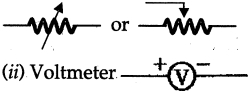
$(i)$ Variable resistance.
$(ii)$ Voltmeter.
$(c)$ An electric bulb is rated $220 \, V$ and $100 \, W$. When it is operated on $110 \, V$,what will be the power consumed?
$(b)$ Write symbols used in electric circuits to represent:
$(i)$ Variable resistance.
$(ii)$ Voltmeter.
$(c)$ An electric bulb is rated $220 \, V$ and $100 \, W$. When it is operated on $110 \, V$,what will be the power consumed?
Solution
(N/A) $Ohm's$ law states that the current flowing through a conductor is directly proportional to the potential difference across its ends,provided the temperature and other physical conditions remain constant.
Mathematically: $V = IR$,where $V$ is potential difference,$I$ is current,and $R$ is resistance.
$(b)$ $(i)$ Variable resistance: Represented by a resistor symbol with an arrow or a sliding contact.
$(ii)$ Voltmeter: Represented by a circle with a '$V$' inside,having positive and negative terminals.
$(c)$ Given: Rated power $P = 100 \, W$,Rated voltage $V = 220 \, V$.
First,calculate the resistance of the bulb:
$R = \frac{V^2}{P} = \frac{(220)^2}{100} = \frac{48400}{100} = 484 \, \Omega$.
Now,calculate the power consumed at $V_1 = 110 \, V$:
$P_{new} = \frac{V_1^2}{R} = \frac{(110)^2}{484} = \frac{12100}{484} = 25 \, W$.
The power consumed will be $25 \, W$.
0 likes
View Solution18
Medium
$(a)$ Name an instrument that measures electric current in a circuit. Define the unit of electric current.
$(b)$ What do the following symbols mean in an electric circuit?
$(c)$ Draw a closed circuit diagram consisting of a $0.5\, m$ long nichrome wire $XY$,an ammeter,a voltmeter,four cells of $1.5\, V$ each,and a plug key.
$(b)$ What do the following symbols mean in an electric circuit?
$(c)$ Draw a closed circuit diagram consisting of a $0.5\, m$ long nichrome wire $XY$,an ammeter,a voltmeter,four cells of $1.5\, V$ each,and a plug key.

Solution
(N/A) The instrument used to measure electric current in a circuit is an ammeter.
The unit of electric current is the ampere $(A)$. One ampere is defined as the flow of $1$ coulomb of electric charge through a cross-section of a conductor in $1$ second.
$(b)$ $(i)$ The symbol represents a rheostat or variable resistance.
$(ii)$ The symbol represents a closed plug key or a closed switch.
$(c)$ The circuit diagram consists of a battery of four cells (total $6\, V$),a plug key (closed),an ammeter connected in series with the $0.5\, m$ nichrome wire $XY$,and a voltmeter connected in parallel across the wire $XY$.
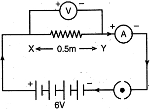
0 likes
View Solution19
Medium
$(a)$ Name an instrument that measures potential difference between two points in a circuit. Define the unit of potential difference in terms of $SI$ unit of charge and work. Draw the circuit symbols for $(i)$ variable resistor,$(ii)$ a plug key which is closed.
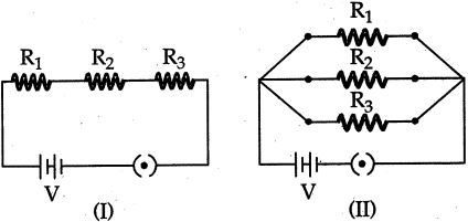
$(b)$ Two electric circuits $(I)$ and $(II)$ are shown below.
$(i)$ Which of the two circuits has more resistance?
$(ii)$ Through which circuit does more current pass?
$(iii)$ In which circuit is the potential difference across each resistor equal?
$(iv)$ If $R_{1} > R_{2} > R_{3}$,in which circuit will more heat be produced in $R_{1}$ as compared to the other two resistors?
Solution
(A) The instrument used to measure the potential difference between two points in a circuit is a Voltmeter.
The $SI$ unit of potential difference is the Volt $(V)$. It is defined as the amount of work done $(W)$ in moving a unit positive charge $(q)$ from one point to another,i.e.,$V = \frac{W}{q}$. Thus,$1 \text{ Volt} = 1 \text{ Joule} / 1 \text{ Coulomb}$.
The circuit symbols are:
$(i)$ Variable resistor: $A$ resistor symbol with an arrow pointing across it.
$(ii)$ Closed plug key: $A$ circle with a dot inside it.
$(b)$ $(i)$ Circuit $(I)$ has more resistance because the resistors are connected in series,and the equivalent resistance is the sum of individual resistances $(R_{eq} = R_{1} + R_{2} + R_{3})$.
$(ii)$ More current passes through circuit $(II)$ because the equivalent resistance in parallel is less than the individual resistances,leading to a higher total current from the source.
$(iii)$ In circuit $(II)$,the potential difference across each resistor is equal because they are connected in parallel.
$(iv)$ In circuit $(I)$,more heat is produced in $R_{1}$ because in a series circuit,the current $(I)$ is the same through all resistors,and heat produced $H = I^{2}Rt$. Since $R_{1}$ is the largest resistance,it will produce the most heat.

0 likes
View Solution20
Medium
$(a)$ What is meant by saying that the potential difference between two points is $1$ volt?
$(b)$ Why does the connecting cord of an electrical heater not glow while the heating element does?
$(c)$ Electrical resistivities of some substances at $20^{\circ}C$ are given below:
Answer the following questions in relation to them:
$(i)$ Among silver and copper, which one is a better conductor? Why?
$(ii)$ Which material would you advise to use in electrical heating devices? Why?
$(b)$ Why does the connecting cord of an electrical heater not glow while the heating element does?
$(c)$ Electrical resistivities of some substances at $20^{\circ}C$ are given below:
| Silver | $1.60 \times 10^{-8} \, \Omega m$ |
| Copper | $1.62 \times 10^{-8} \, \Omega m$ |
| Tungsten | $5.2 \times 10^{-8} \, \Omega m$ |
| Iron | $10.0 \times 10^{-8} \, \Omega m$ |
| Mercury | $94.0 \times 10^{-8} \, \Omega m$ |
| Nichrome | $100 \times 10^{-6} \, \Omega m$ |
Answer the following questions in relation to them:
$(i)$ Among silver and copper, which one is a better conductor? Why?
$(ii)$ Which material would you advise to use in electrical heating devices? Why?
Solution
(N/A) The potential difference between two points is said to be $1$ volt if $1$ joule of work is done in moving a charge of $1$ coulomb from one point to another.
$(b)$ The heating element of an electrical heater is made of an alloy (like nichrome) which has high resistivity. Due to high resistivity, it produces a large amount of heat when current passes through it, causing it to glow. In contrast, the connecting cord is made of copper, which has very low resistivity, so it does not produce significant heat and does not glow.
$(c)$ $(i)$ Silver is a better conductor than copper because it has lower electrical resistivity ($1.60 \times 10^{-8} \, \Omega m$ for silver vs $1.62 \times 10^{-8} \, \Omega m$ for copper).
$(ii)$ Nichrome is advised for electrical heating devices because it has a very high resistivity compared to other materials listed, which allows it to generate more heat according to Joule's law of heating $(H = I^2Rt)$.
0 likes
View Solution21
Difficult
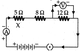
Draw a schematic diagram of an electric circuit (in the "on" position) consisting of a battery of five cells of $2\, V$ each, a $5\, \Omega$ resistor, a $8\, \Omega$ resistor, a $12\, \Omega$ resistor and a plug key, all connected in series. An ammeter is put in the circuit to measure the electric current through the resistors and a voltmeter is connected so as to measure the potential difference across the $12\, \Omega$ resistor.
Calculate the reading shown by the
$(a)$ ammeter
$(b)$ voltmeter in the given electric circuit.
Calculate the reading shown by the
$(a)$ ammeter
$(b)$ voltmeter in the given electric circuit.
Solution
$(a)$ Total resistance $R = 5\, \Omega + 8\, \Omega + 12\, \Omega = 25\, \Omega$.
Total voltage $V = 5 \times 2\, V = 10\, V$.
Using Ohm's law, the current $I = \frac{V}{R} = \frac{10\, V}{25\, \Omega} = 0.4\, A$.
Therefore, the ammeter reading is $0.4\, A$.
$(b)$ The potential difference across the $12\, \Omega$ resistor is $V' = I \times R_{12} = 0.4\, A \times 12\, \Omega = 4.8\, V$.
Therefore, the voltmeter reading is $4.8\, V$.
0 likes
View Solution22
Difficult
$(a)$ Explain how a cell maintains current in a circuit.
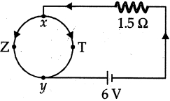
$(b)$ In the circuit given below,the resistance of the path $xTy = 2 \, \Omega$ and that of $xZy = 6 \, \Omega$.
$(i)$ Find the equivalent resistance between $x$ and $y$.
$(ii)$ Find the current in the main circuit.
$(iii)$ Calculate the current that flows through the path $xTy$ and $xZy$.
$(b)$ In the circuit given below,the resistance of the path $xTy = 2 \, \Omega$ and that of $xZy = 6 \, \Omega$.
$(i)$ Find the equivalent resistance between $x$ and $y$.
$(ii)$ Find the current in the main circuit.
$(iii)$ Calculate the current that flows through the path $xTy$ and $xZy$.
Solution
(N/A) The chemical action within a cell generates a potential difference across its terminals. This potential difference drives and maintains the flow of electric current in the circuit.
$(b)$ $(i)$ The paths $xTy$ and $xZy$ are connected in parallel between points $x$ and $y$. The equivalent resistance $R_e$ is given by:
$\frac{1}{R_e} = \frac{1}{2} + \frac{1}{6} = \frac{3+1}{6} = \frac{4}{6} = \frac{2}{3} \, \Omega^{-1}$
$R_e = 1.5 \, \Omega$
$(ii)$ The total resistance of the circuit is the sum of the equivalent resistance $R_e$ and the series resistor of $1.5 \, \Omega$:
$R_{total} = 1.5 \, \Omega + 1.5 \, \Omega = 3 \, \Omega$
Using Ohm's law,the main current $I = \frac{V}{R_{total}} = \frac{6 \, V}{3 \, \Omega} = 2 \, A$
$(iii)$ The potential difference across the parallel combination of $xTy$ and $xZy$ is $V_{xy} = I \times R_e = 2 \, A \times 1.5 \, \Omega = 3 \, V$.
Current through path $xTy$ $(2 \, \Omega)$: $I_1 = \frac{V_{xy}}{R_1} = \frac{3 \, V}{2 \, \Omega} = 1.5 \, A$
Current through path $xZy$ $(6 \, \Omega)$: $I_2 = \frac{V_{xy}}{R_2} = \frac{3 \, V}{6 \, \Omega} = 0.5 \, A$
0 likes
View Solution23
Difficult
$(a)$ $(i)$ What is meant by saying that the potential difference between two points is $1 \, V$? $(ii)$ How much energy is given to $5 \, C$ of charge passing through a $12 \, V$ battery? $(b)$ Describe an activity with a necessary electric circuit to study the factors on which the resistance of a conducting wire depends.
Solution
(A) $(i)$ It means that the work done in moving a charge of $1 \, C$ between the two points is $1 \, J$.
$(ii)$ Using the formula $W = qV$,where $q = 5 \, C$ and $V = 12 \, V$,we get $W = 5 \times 12 = 60 \, J$.
$(b)$ To study the factors affecting resistance:
$(i)$ Set up a circuit with a cell,an ammeter,a nichrome wire of length $l$,and a plug key.
$(ii)$ Close the key and note the current reading in the ammeter.
$(iii)$ Replace the wire with another nichrome wire of the same thickness but double the length $(2l)$. Note the current.
$(iv)$ Replace the wire with a thicker nichrome wire of the same length $l$. Note the current.
$(v)$ Replace the wire with a copper wire of the same length and thickness as the first nichrome wire. Note the current.
$(vi)$ Observe that the current varies in each case,demonstrating that resistance depends on length,cross-sectional area,and the material of the conductor.
1 likes
View Solution24
Medium
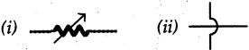
$(a)$ What do the following symbols represent in a circuit? Write the name and one function of each.
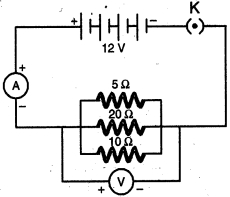
$(b)$ Draw a schematic diagram of a circuit consisting of a battery of $12 \, V$,three resistors of $5 \, \Omega$,$10 \, \Omega$,and $20 \, \Omega$ connected in parallel,an ammeter to measure the total current through the circuit,and a voltmeter to measure the potential difference across the combination of resistors.
$(c)$ State any one advantage of connecting electrical devices in parallel with the mains instead of connecting them in series in a household circuit.
Solution
(N/A) $(i)$ Variable resistor or rheostat: It is used to change the resistance in a circuit,thereby controlling the current flowing through it.
$(ii)$ Wires crossing without joining: It represents two wires that cross each other without making any electrical contact.
$(b)$ The circuit diagram consists of a $12 \, V$ battery,a switch $(K)$,an ammeter $(A)$ in series with the combination,and a voltmeter $(V)$ connected in parallel across the three resistors ($5 \, \Omega$,$10 \, \Omega$,and $20 \, \Omega$) which are themselves connected in parallel.
$(c)$ Advantage of parallel connection: In a parallel circuit,if one electrical device stops working due to a defect or switch-off,the other devices continue to operate independently because each device has its own separate circuit path.
0 likes
View Solution25
Medium
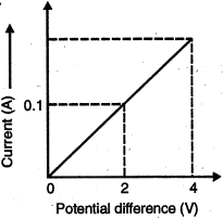
$(a)$ Calculate the resistance of the wire using the graph.
$(b)$ How many $176 \,\Omega$ resistors in parallel are required to carry $5\, A$ on a $220\, V$ line?
$(c)$ Define electric power. Derive the relation between power,potential difference,and resistance.
$(b)$ How many $176 \,\Omega$ resistors in parallel are required to carry $5\, A$ on a $220\, V$ line?
$(c)$ Define electric power. Derive the relation between power,potential difference,and resistance.
Solution
(N/A) The resistance $R$ is given by Ohm's law: $R = V / I$.
From the graph,at $V = 2 \, V$,the current $I = 0.1 \, A$.
Therefore,$R = 2 \, V / 0.1 \, A = 20 \, \Omega$.
$(b)$ Given: Total current $I = 5 \, A$,Voltage $V = 220 \, V$.
The required total resistance $R_{eq}$ of the circuit is $R_{eq} = V / I = 220 \, V / 5 \, A = 44 \, \Omega$.
Let $n$ resistors of $176 \, \Omega$ each be connected in parallel.
The equivalent resistance for $n$ resistors in parallel is $1 / R_{eq} = n / R$.
$1 / 44 = n / 176$.
$n = 176 / 44 = 4$.
Thus,$4$ resistors are required.
$(c)$ Electric power is defined as the rate at which electric energy is dissipated or consumed in an electric circuit.
We know that power $P = W / t$ and work done $W = V \cdot I \cdot t$.
So,$P = (V \cdot I \cdot t) / t = V \cdot I$.
From Ohm's law,$I = V / R$.
Substituting $I$ in the power equation: $P = V \cdot (V / R) = V^2 / R$.
0 likes
View Solution26
Medium
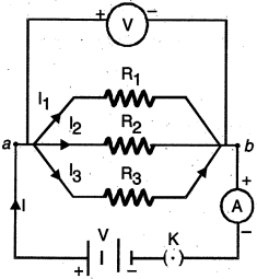
$(a)$ Three resistors $R_{1}, R_{2}$ and $R_{3}$ are connected in parallel and the combination is connected to a battery,ammeter,voltmeter,and key. Draw a suitable circuit diagram. Obtain an expression for the effective resistance of the combination of resistors in parallel.
$(b)$ Why are electric bulbs filled with chemically inactive nitrogen or argon?
$(c)$ What is meant by the statement that the rating of a fuse in a circuit is $5 \ A$?
$(b)$ Why are electric bulbs filled with chemically inactive nitrogen or argon?
$(c)$ What is meant by the statement that the rating of a fuse in a circuit is $5 \ A$?
Solution
(N/A) The circuit diagram shows three resistors $R_{1}, R_{2}, R_{3}$ connected in parallel across a potential difference $V$. The total current $I$ splits into $I_{1}, I_{2}, I_{3}$ through the resistors.
Since they are in parallel,the potential difference $V$ across each resistor is the same.
Total current $I = I_{1} + I_{2} + I_{3}$.
Using Ohm's law,$I_{1} = V/R_{1}$,$I_{2} = V/R_{2}$,and $I_{3} = V/R_{3}$.
If $R_{p}$ is the equivalent resistance,$I = V/R_{p}$.
Substituting these,$V/R_{p} = V/R_{1} + V/R_{2} + V/R_{3}$.
Thus,$1/R_{p} = 1/R_{1} + 1/R_{2} + 1/R_{3}$.
$(b)$ Electric bulbs are filled with chemically inactive gases like nitrogen or argon to prevent the oxidation of the tungsten filament at high temperatures,thereby prolonging its life.
$(c)$ The statement means that the fuse is designed to allow a maximum current of $5 \ A$ to flow through the circuit. If the current exceeds this value,the fuse wire melts due to excessive heating and breaks the circuit,protecting the appliances.
0 likes
View Solution27
Medium
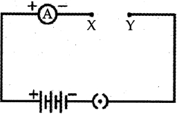
$(a)$ In the circuit shown, connect a nichrome wire of length $L$ between points $X$ and $Y$ and note the ammeter reading.
$(i)$ When this experiment is repeated by inserting another nichrome wire of the same thickness but twice the length $(2L)$, what changes are observed in the ammeter reading?
$(ii)$ State the changes that are observed in the ammeter reading if we double the area of cross-section without changing the length in the above experiment. Justify your answer in both cases.
$(b)$ "Potential difference between points $A$ and $B$ in an electric field is $1\, V$." Explain the statement.
Solution
(N/A) $(i)$ The ammeter reading will decrease (become half). This is because resistance $R$ is directly proportional to length $L$ $(R \propto L)$. When length is doubled, resistance doubles, and according to Ohm's law $(I = V/R)$, the current $I$ becomes half.
$(ii)$ The ammeter reading will increase (become two times). This is because resistance $R$ is inversely proportional to the area of cross-section $A$ $(R \propto 1/A)$. When the area is doubled, resistance becomes half, and consequently, the current $I$ becomes double.
$(b)$ It means that $1\, J$ of work is being done to move a charge of $1\, C$ from point $A$ to point $B$.
0 likes
View Solution28
Medium
Draw a circuit diagram for a circuit consisting of a battery of five cells of $2 \text{ V}$ each, a $5 \, \Omega$ resistor, a $10 \, \Omega$ resistor, and a $15 \, \Omega$ resistor, an ammeter, and a plug key; all connected in series. Also, connect a voltmeter to record the potential difference across the $15 \, \Omega$ resistor and calculate:
$(i)$ the electric current passing through the above circuit and
$(ii)$ the potential difference across the $5 \, \Omega$ resistor when the key is closed.
$(i)$ the electric current passing through the above circuit and
$(ii)$ the potential difference across the $5 \, \Omega$ resistor when the key is closed.
Solution
(A) The circuit diagram is as shown in the provided image.
Given:
Total voltage $V = 5 \times 2 \text{ V} = 10 \text{ V}$.
Resistors in series: $R_{1} = 5 \, \Omega$, $R_{2} = 10 \, \Omega$, $R_{3} = 15 \, \Omega$.
The equivalent resistance $R$ of the series combination is:
$R = R_{1} + R_{2} + R_{3} = 5 + 10 + 15 = 30 \, \Omega$.
$(i)$ The electric current $I$ passing through the circuit is:
$I = V / R = 10 \text{ V} / 30 \, \Omega = 1/3 \text{ A} \approx 0.33 \text{ A}$.
$(ii)$ The potential difference $V_{1}$ across the $5 \, \Omega$ resistor is:
$V_{1} = I \times R_{1} = (1/3) \text{ A} \times 5 \, \Omega = 5/3 \text{ V} \approx 1.67 \text{ V}$.
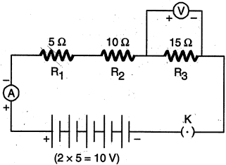
0 likes
View Solution29
Medium
$(a)$ What is an electric circuit?
$(b)$ Calculate the number of electrons that flow per second to constitute a current of one ampere. The charge on an electron is $1.6 \times 10^{-19} \ C$.
$(c)$ Draw an electric circuit for studying Ohm's law. Label the circuit components used to measure electric current and potential difference.
$(b)$ Calculate the number of electrons that flow per second to constitute a current of one ampere. The charge on an electron is $1.6 \times 10^{-19} \ C$.
$(c)$ Draw an electric circuit for studying Ohm's law. Label the circuit components used to measure electric current and potential difference.
Solution
(N/A) An electric circuit is a continuous and closed path in which an electric current can flow.
$(b)$ We know that $I = Q / t$ and $Q = n e$,where $n$ is the number of electrons and $e$ is the charge on an electron. Therefore,we have:
$I = n e / t$
$n = (I \times t) / e = (1 \ \text{A} \times 1 \ \text{s}) / (1.6 \times 10^{-19} \ \text{C})$
$n = 6.25 \times 10^{18}$ electrons.
$(c)$ The circuit diagram used to study Ohm's law is shown below.
Electric current is measured by an Ammeter $(A)$.
Potential difference is measured by a Voltmeter $(V)$.
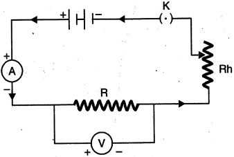
0 likes
View Solution30
Medium
State $Ohm's$ law. Write the mathematical representation of $Ohm's$ law. Use this relationship to define $1\, ohm.$ List two disadvantages of connecting different electrical appliances in series.
Solution
(N/A) $Ohm's$ law: The potential difference across the ends of a resistor is directly proportional to the current flowing through it, provided its temperature remains constant.
Mathematical representation: $V = IR$ or $R = V / I$, where $V$ is the potential difference, $I$ is the current, and $R$ is the resistance.
Definition of $1\, ohm$: If the potential difference across the two ends of a conductor is $1\, V$ and the current flowing through it is $1\, A$, then the resistance $R$ of the conductor is $1\, ohm$ $(1\, \Omega = 1\, V / 1\, A)$.
Disadvantages of series connection:
$(i)$ Different electrical appliances require different values of current to operate properly, which is not possible in a series circuit because the current remains the same throughout.
$(ii)$ If one appliance fails or is switched off, the entire circuit is broken, and none of the other appliances will work.
0 likes
View Solution31
Medium
$(a)$ Derive an expression to find the equivalent resistance of three resistors connected in series. Also,draw the schematic diagram of the circuit.
$(b)$ Find the equivalent resistance of the following circuit.
$(b)$ Find the equivalent resistance of the following circuit.
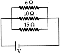
Solution
(N/A) When three resistors $R_1, R_2,$ and $R_3$ are connected in series,the same current $I$ flows through each resistor. The potential difference across each resistor is $V_1 = IR_1, V_2 = IR_2,$ and $V_3 = IR_3$. The total potential difference $V$ is $V = V_1 + V_2 + V_3 = I(R_1 + R_2 + R_3)$. If $R_s$ is the equivalent resistance,then $V = IR_s$. Thus,$R_s = R_1 + R_2 + R_3$.
$(b)$ The given circuit shows three resistors connected in parallel with values $R_1 = 6 \Omega, R_2 = 10 \Omega,$ and $R_3 = 15 \Omega$.
For parallel connection,the equivalent resistance $R_p$ is given by:
$\frac{1}{R_p} = \frac{1}{R_1} + \frac{1}{R_2} + \frac{1}{R_3}$
$\frac{1}{R_p} = \frac{1}{6} + \frac{1}{10} + \frac{1}{15}$
$\frac{1}{R_p} = \frac{5 + 3 + 2}{30} = \frac{10}{30} = \frac{1}{3}$
Therefore,$R_p = 3 \Omega$.
0 likes
View Solution32
Medium
Two resistors are connected in series as shown in the diagram. $(i)$ What is the current through the $5 \, \Omega$ resistor? (ii) What is the current through $R$? (iii) What is the value of $R$? (iv) What is the value of $V$?
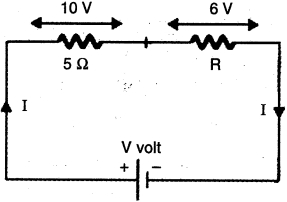
Solution
(A) Given:
Potential difference across $5 \, \Omega$ resistor $(V_1)$ = $10 \, V$
Potential difference across $R \, \Omega$ resistor $(V_2)$ = $6 \, V$
Resistance $R_1 = 5 \, \Omega$
$(i)$ By Ohm's law,the current $(I)$ through the $5 \, \Omega$ resistor is:
$I = \frac{V_1}{R_1} = \frac{10 \, V}{5 \, \Omega} = 2 \, A$
(ii) Since the two resistors are connected in series,the current remains the same throughout the circuit. Therefore,the current through resistor $R$ is also $2 \, A$.
(iii) Using Ohm's law for resistor $R$:
$R = \frac{V_2}{I} = \frac{6 \, V}{2 \, A} = 3 \, \Omega$
(iv) Since the resistors are in series,the total voltage $V$ is the sum of the potential differences across each resistor:
$V = V_1 + V_2 = 10 \, V + 6 \, V = 16 \, V$
0 likes
View Solution33
DifficultMCQ
$A$ torch bulb is rated $5\,V$ and $500\,mA$. Calculate its $(i)$ power,$(ii)$ resistance,and $(iii)$ energy consumed when it is lighted for $4$ hours.
A
$2.5\,W, 10\,\Omega, 36000\,J$
B
$5\,W, 5\,\Omega, 18000\,J$
C
$1.25\,W, 20\,\Omega, 72000\,J$
D
$2.5\,W, 5\,\Omega, 10000\,J$
Solution
(A) Given: Voltage $V = 5\,V$,Current $I = 500\,mA = 0.5\,A$,Time $t = 4\,\text{hours} = 4 \times 3600\,s = 14400\,s$.
$(i)$ Power $P = V \times I = 5\,V \times 0.5\,A = 2.5\,W$.
$(ii)$ Resistance $R = V / I = 5\,V / 0.5\,A = 10\,\Omega$.
$(iii)$ Energy consumed $E = P \times t = 2.5\,W \times 14400\,s = 36000\,J$.
$(i)$ Power $P = V \times I = 5\,V \times 0.5\,A = 2.5\,W$.
$(ii)$ Resistance $R = V / I = 5\,V / 0.5\,A = 10\,\Omega$.
$(iii)$ Energy consumed $E = P \times t = 2.5\,W \times 14400\,s = 36000\,J$.
0 likes
View Solution34
MediumMCQ
Two electric lamps of $100\, W$ and $25\, W$ respectively are joined in parallel to a supply of $200\, V$. Calculate the total current flowing through the circuit. (in $, A$)
A
$0.5$
B
$0.625$
C
$0.75$
D
$0.8$
Solution
(B) When electric lamps are connected in parallel,the total power consumed by the circuit is the sum of the power of individual lamps.
Total power,$P = P_{1} + P_{2} = 100\, W + 25\, W = 125\, W$.
The relationship between power $(P)$,voltage $(V)$,and current $(I)$ is given by the formula $P = V \times I$.
To find the total current $(I)$,we rearrange the formula: $I = \frac{P}{V}$.
Substituting the given values: $I = \frac{125\, W}{200\, V} = 0.625\, A$.
Therefore,the total current flowing through the circuit is $0.625\, A$.
0 likes
View Solution35
Easy
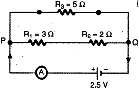
In the given circuit,calculate $(i)$ total resistance of the circuit,and (ii) current shown by the ammeter.
Solution
(N/A) $(i)$ Since $R_{1}$ and $R_{2}$ are in series,their resultant resistance,
$R_{S} = R_{1} + R_{2} = 3 + 2 = 5 \Omega$
Further,$R_{S}$ and $R_{3}$ are in parallel,their resultant resistance is given by
$R_{P} = \frac{R_{S} \times R_{3}}{R_{S} + R_{3}} = \frac{5 \times 5}{5 + 5} = 2.5 \Omega$
(ii) Also,the current $I$ shown by the ammeter is given by Ohm's law:
$I = \frac{V}{R_{P}} = \frac{2.5 \text{ V}}{2.5 \Omega} = 1 \text{ A}$
0 likes
View Solution36
Medium
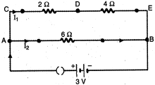
In the circuit shown below, calculate:
$(a)$ total resistance in arm $CE$,
$(b)$ total current drawn from the battery, and
$(c)$ current in each arm, i.e., $AB$ and $CE$ of the circuit.
$(a)$ total resistance in arm $CE$,
$(b)$ total current drawn from the battery, and
$(c)$ current in each arm, i.e., $AB$ and $CE$ of the circuit.
Solution
(N/A) In arm $CE$, the resistors of value $2 \, \Omega$ and $4 \, \Omega$ are connected in series. Therefore, the total resistance in arm $CE = 2 \, \Omega + 4 \, \Omega = 6 \, \Omega$.
$(b)$ The circuit consists of two parallel branches, arm $CE$ and arm $AB$, each having a resistance of $6 \, \Omega$. The total resistance of the circuit $R_P$ is given by:
$R_P = \frac{6 \, \Omega \times 6 \, \Omega}{6 \, \Omega + 6 \, \Omega} = 3 \, \Omega$.
Therefore, the total current $I$ drawn from the battery is:
$I = \frac{V}{R_P} = \frac{3 \, V}{3 \, \Omega} = 1 \, A$.
$(c)$ Since both arms $CE$ and $AB$ have the same resistance $(6 \, \Omega)$, the total current is split equally between them. Hence, the current in each arm ($AB$ and $CE$) is $0.5 \, A$.
0 likes
View Solution37
Medium
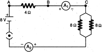
Find out the following in the electric circuit given in the figure:
$(a)$ Effective resistance of two $8\, \Omega$ resistors in the combination.
$(b)$ Current flowing through $4\, \Omega$ resistor.
$(c)$ Potential difference across $4\, \Omega$ resistor.
$(d)$ Power dissipated in $4\, \Omega$ resistor.
$(e)$ Difference in ammeter readings,if any.
$(a)$ Effective resistance of two $8\, \Omega$ resistors in the combination.
$(b)$ Current flowing through $4\, \Omega$ resistor.
$(c)$ Potential difference across $4\, \Omega$ resistor.
$(d)$ Power dissipated in $4\, \Omega$ resistor.
$(e)$ Difference in ammeter readings,if any.
Solution
(N/A) The two $8\, \Omega$ resistors are connected in parallel. Their effective resistance $R_P$ is given by:
$R_P = \frac{R_1 R_2}{R_1 + R_2} = \frac{8 \times 8}{8 + 8} = \frac{64}{16} = 4\, \Omega$
$(b)$ The total resistance of the circuit $R_{eq} = R_{series} + R_P = 4\, \Omega + 4\, \Omega = 8\, \Omega$. The total current $I$ in the circuit is:
$I = \frac{V}{R_{eq}} = \frac{8\, V}{8\, \Omega} = 1\, A$. Since the $4\, \Omega$ resistor is in series with the rest of the circuit,the same current flows through it.
$(c)$ The potential difference $V$ across the $4\, \Omega$ resistor is:
$V = I \times R = 1\, A \times 4\, \Omega = 4\, V$
$(d)$ The power $P$ dissipated in the $4\, \Omega$ resistor is:
$P = I^2 R = (1\, A)^2 \times 4\, \Omega = 4\, W$
$(e)$ There is no difference in the ammeter readings. In a series circuit,the current remains the same at all points,so both ammeters $A_1$ and $A_2$ will show the same reading of $1\, A$.
0 likes
View Solution38
Medium
An electric oven hot plate is connected to a $200 \, V$ line. It has two resistance coils $A$ and $B$,each of $30 \, \Omega$,which may be used separately,in series,or in parallel. Find the value of the current required in each of the three cases.
Solution
(N/A) Given: Voltage $V = 200 \, V$,Resistance of coil $A$ $(R_A)$ = $30 \, \Omega$,Resistance of coil $B$ $(R_B)$ = $30 \, \Omega$.
$(i)$ When coil $A$ or $B$ is used separately:
$I = V / R = 200 / 30 = 6.67 \, A$.
(ii) When the coils are connected in series:
Total resistance $R_S = R_A + R_B = 30 + 30 = 60 \, \Omega$.
$I_S = V / R_S = 200 / 60 = 3.33 \, A$.
(iii) When the coils are connected in parallel:
Total resistance $1 / R_P = 1 / R_A + 1 / R_B = 1 / 30 + 1 / 30 = 2 / 30 = 1 / 15$.
$R_P = 15 \, \Omega$.
$I_P = V / R_P = 200 / 15 = 13.33 \, A$.
0 likes
View Solution39
Medium
The table given below provides the resistivity of three samples in $\Omega \cdot m$:
$(a)$ Which of them is a good conductor? Which is an insulator? Why?
$(b)$ $A$ wire of resistance $4 \ \Omega$ is folded on itself to double its thickness. Calculate the new resistance of the wire.
| Sample | Resistivity $(\Omega \cdot m)$ |
| $A$ | $1.6 \times 10^{-8}$ |
| $B$ | $7.5 \times 10^{17}$ |
| $C$ | $44 \times 10^{-6}$ |
$(a)$ Which of them is a good conductor? Which is an insulator? Why?
$(b)$ $A$ wire of resistance $4 \ \Omega$ is folded on itself to double its thickness. Calculate the new resistance of the wire.
Solution
$(A)$ Sample $A$ is a good conductor, and sample $B$ is an insulator.
Metals and alloys typically have low resistivity in the range of $10^{-8} \ \Omega \cdot m$ to $10^{-6} \ \Omega \cdot m$, making them good conductors of electricity. In contrast, insulators possess very high resistivity, typically in the order of $10^{12} \ \Omega \cdot m$ to $10^{17} \ \Omega \cdot m$.
$(b)$ When a wire of resistance $R = 4 \ \Omega$ is folded on itself, its length $l$ becomes $l' = l/2$ and its cross-sectional area $A$ becomes $A' = 2A$.
The resistance formula is $R = \rho (l/A)$.
The new resistance $R'$ is given by:
$R' = \rho (l'/A') = \rho ((l/2) / (2A)) = (1/4) \times \rho (l/A) = R/4$.
Substituting $R = 4 \ \Omega$:
$R' = 4 \ \Omega / 4 = 1 \ \Omega$.
Therefore, the new resistance is $1 \ \Omega$.
0 likes
View Solution40
Medium
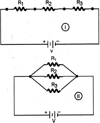
Two electric circuits $I$ and $II$ are shown in the figure.
$(i)$ Which of the two circuits has more resistance?
$(ii)$ Through which circuit does more current pass?
$(iii)$ In which circuit is the potential difference across each resistor equal?
$(i)$ Which of the two circuits has more resistance?
$(ii)$ Through which circuit does more current pass?
$(iii)$ In which circuit is the potential difference across each resistor equal?
Solution
(N/A) $(i)$ The net resistance of a series combination of resistors is greater than the net resistance of a parallel combination of resistors. Therefore,the resistance of circuit $I$ is greater than the resistance of circuit $II$.
$(ii)$ Since current is inversely proportional to resistance for the same potential difference $(I = V/R)$,the current in circuit $II$ is greater than the current in circuit $I$.
$(iii)$ In a parallel circuit,the potential difference across each resistor is equal. Therefore,the potential difference across each resistor in circuit $II$ is equal.
0 likes
View Solution41
Medium
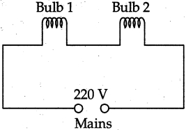
An electric bulb rated $220 \, V, 60 \, W$ is working at full efficiency. $(i)$ State the resistance of the coil of the bulb. Another identical bulb is connected in series with the first one and the system is connected across the mains as shown below. $(ii)$ State the rate of conversion of energy in each bulb. $(iii)$ Calculate the total power. $(iv)$ What will be the total power if the bulbs are connected in parallel?
Solution
(N/A) Given: Rated voltage $V = 220 \, V$,Rated power $P = 60 \, W$.
$(i)$ Using the formula $P = \frac{V^2}{R}$,the resistance $R$ of the bulb is:
$R = \frac{V^2}{P} = \frac{(220)^2}{60} = \frac{48400}{60} \approx 806.67 \, \Omega$.
$(ii)$ When two identical bulbs are connected in series,the total resistance $R_T = R + R = 2R = 2 \times 806.67 = 1613.34 \, \Omega$.
The current $I$ flowing through the circuit is $I = \frac{V}{R_T} = \frac{220}{1613.34} \approx 0.136 \, A$.
The rate of energy conversion (power consumed) in each bulb is $P' = I^2 R = (0.136)^2 \times 806.67 \approx 15 \, W$.
$(iii)$ Total power consumed in series connection is $P_{total} = I^2 R_T = (0.136)^2 \times 1613.34 \approx 30 \, W$.
$(iv)$ If the bulbs are connected in parallel,the total power is $P_{total} = P_1 + P_2 = 60 + 60 = 120 \, W$.
0 likes
View Solution42
EasyMCQ
Which of the following is the symbol for a resistor?
A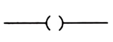
Open switch
B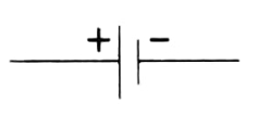
Cell
C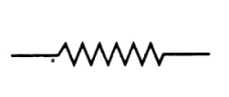
Resistor
D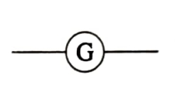
Galvanometer
Solution
(C) In electrical circuit diagrams,different components are represented by standard symbols.
- The symbol shown in option $A$ represents an open switch.
- The symbol shown in option $B$ represents a cell.
- The symbol shown in option $C$ represents a resistor,which is a component used to provide resistance in a circuit.
- The symbol shown in option $D$ represents a galvanometer,used to detect small electric currents.
Therefore,the correct symbol for a resistor is given in option $C$.
0 likes
View Solution43
MCQ
Sonika is working with the circuit shown in the figure. There are two open terminals in the circuit: $X$ and $Y$. She has wires made of five different materials: $I, II, III, IV,$ and $V$. She knows that the electric bulb will glow only when wires made of conducting materials are connected across both open terminals. She records her observations in a table. After the experiment,ink spills on the paper,and she loses the information for the third row.
Based on the remaining information in the table,which materials could be in the third row?
| $S.No.$ | Material at $X$ | Material at $Y$ | Electric Bulb ($ON$/$OFF$) |
| $1$ | $I$ | $II$ | $OFF$ |
| $2$ | $I$ | $IV$ | $ON$ |
| $3$ | - | - | $OFF$ |
| $4$ | $III$ | $V$ | $ON$ |
Based on the remaining information in the table,which materials could be in the third row?
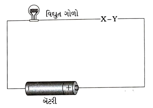
A
$II$ and $III$
B
$III$ and $IV$
C
$IV$ and $V$
D
$I$ and $III$
Solution
(A) $1$. Analyze the observations: The bulb glows $(ON)$ only if both materials connected at $X$ and $Y$ are conductors. If the bulb is $OFF$,it means at least one of the materials is an insulator.
$2$. From observation $2$,$I$ and $IV$ result in $ON$,so both $I$ and $IV$ are conductors.
$3$. From observation $4$,$III$ and $V$ result in $ON$,so both $III$ and $V$ are conductors.
$4$. From observation $1$,$I$ and $II$ result in $OFF$. Since $I$ is a conductor,$II$ must be an insulator.
$5$. For the third row,the bulb is $OFF$. This means at least one of the materials must be an insulator. Since $II$ is the only identified insulator,the pair must contain $II$.
$6$. Looking at the options,option $A$ ($II$ and $III$) contains $II$,which is an insulator. Therefore,the bulb will remain $OFF$.
0 likes
View SolutionElectricity — Mix Examples - Electricity · Frequently Asked Questions
1Are these Electricity questions useful for JEE and NEET?
Yes. All questions in this section are mapped to JEE Main and NEET exam patterns. Previous year questions from JEE Main, NEET, GUJCET and state-level exams are included with full solutions.
2Can I switch to Hindi or Gujarati for these questions?
Yes. Use the language tabs in the hero section or the sidebar to view the same questions and solutions in English, Hindi or Gujarati.
3How do I generate a question paper from this subtopic?
Use the Vedclass Exam Paper Generator — select the chapter and subtopic, set difficulty, and generate Sets A, B, C, D automatically. First 3 chapters of every subject are free.
Vedclass Products
For Students
Vedclass Test Series
Mock tests in real JEE/NEET style with performance analysis. 5-day free trial.
Start Free TrialFor Teachers
Exam Paper Generator
Generate Set A/B/C/D papers from this chapter in 2 minutes. 3 chapters free.
Try FreeFor Institutes
Online Exam Module
Live online exams with unlimited students, 360° analytics & white-label branding.
See DemoFor Teachers & Institutes
Generate a Electricity Exam Paper in 2 Minutes
Select subtopic & difficulty — Sets A, B, C, D auto-generated with No Repeat logic.
First 3 chapters of every subject are free — no payment required.